
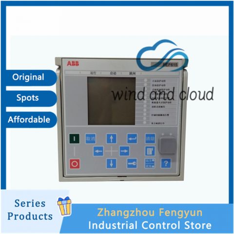
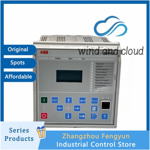
All products on this website are discounted products, and market prices have been fluctuating. Please refer to customer service quotes for details. Pictures are not actual photos. Before placing an order, please confirm the model, product, price, and other detailed information with customer service. Both second-hand and brand new products are available for sale on this website. Please contact customer service for further communication.
ABB REF615C|Feeder Protection and Control|
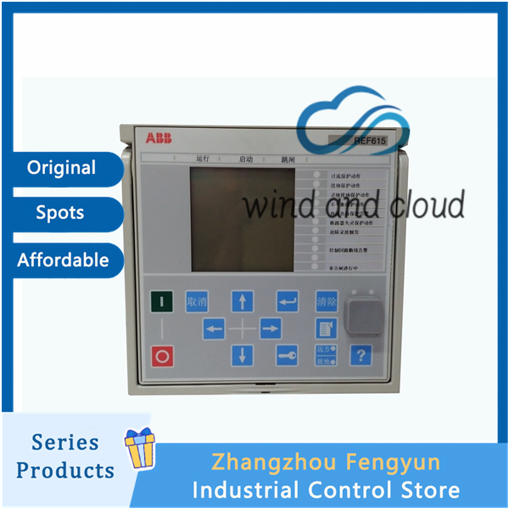
Functional Diagram Overview
The functional diagrams of the ABB REF615 IED provide a graphical representation of the device functionality from multiple engineering perspectives, including:
Protection functions
Measurement functions
Condition monitoring
Disturbance recording
Control functions
Interlocking logic
The diagrams illustrate the default REF615 configuration using simplified logical symbols to represent the internal functional relationships and signal paths.
The functional diagrams also show the external connections to primary electrical equipment, including the default wiring arrangements for:
Current transformers (CTs)
Voltage transformers (VTs)
Binary input signals
Binary output signals
Protection Direction Reference
For directional protection functions, the default positive measurement direction is defined as:
Towards the outgoing feeder
This reference direction is used for functions such as:
Directional overcurrent protection
Directional earth-fault protection
Power-related protection functions
Correct directional configuration ensures that fault direction decisions correspond with the actual feeder topology.
Functional Diagram Structure
The REF615 functional diagrams are divided into separate sections.
Each section represents one functional entity, such as:
Protection stage
Measurement function
Control logic
Monitoring function
Recording function
Input/output interface
The external connections are also divided into corresponding sections.
Only the connections relevant to a specific functional entity are displayed in each section, improving readability and simplifying engineering analysis.
Protection Function Block Identification
Protection function blocks are included directly in the functional diagrams.
Each function block is identified using:
IEC 61850 function name
IEC function symbol
ANSI device/function number
Example:
Identification Method Example
IEC 61850 name PHHPTOC
ANSI function number 50/51
IEC symbol Protection function symbol
This naming method allows engineers to easily correlate the functional diagrams with:
IEC 61850 data models
Protection engineering documents
Relay setting tools
ANSI protection standards
Function Block Instance Numbering
Some protection function blocks may be used multiple times within the same REF615 configuration.
For example:
PHHPTOC
(High-stage phase overcurrent protection)
may appear more than once depending on the selected application configuration.
To distinguish multiple instances, the function block identification includes a sequential instance number.
Example:
PHHPTOC1
PHHPTOC2
PHHPTOC3
The numbering starts from:
1 and increases upward
If a function block does not have an appended number, it means:
The function is used only once in the configuration.
Separation Between Internal Logic and External Connections
The functional diagrams clearly separate:
Internal IED Functionality
Includes:
Protection logic
Control logic
Measurement processing
Internal signals
IEC 61850 logical nodes
External Connections
Includes:
CT/VT inputs
Binary inputs
Binary outputs
External control signals
The separation is represented by a:
Dashed line indicating the physical IED enclosure
This distinction helps engineers understand which signals exist:
Inside the relay
Outside the relay wiring interface
Signal Matrix and Application Configuration
The REF615 standard configuration can be modified using ABB’s PCM600 Protection and Control IED Manager engineering tools.
Two main tools are used:
Signal Matrix
Application Configuration
Signal Matrix Tool
The Signal Matrix tool is used primarily for signal mapping and engineering.
These functions:
Cannot be removed
Remain available even if modification is attempted through Application Configuration
Mandatory blocks are retained because they are required for:
Core relay operation
Communication integrity
System management functions
Engineering Workflow Example
A typical REF615 customization process:
Step Engineering Activity Tool
1 Select standard REF615 configuration PCM600
2 Review default functional diagrams Documentation
3 Modify signal routing Signal Matrix
4 Add/remove application functions Application Configuration
5 Configure IEC 61850 communication PCM600
6 Download configuration to IED PCM600
7 Perform commissioning tests Test equipment
Procurement and Maintenance Considerations
Feature Engineering Benefit
IEC 61850-based function identification Simplifies integration with modern substations
Instance numbering Enables clear identification of duplicated protection stages
Functional diagrams Provides complete protection and control documentation
Signal Matrix customization Simplifies I/O and GOOSE mapping
Application Configuration Enables flexible application modification
Automatic data model update Maintains IEC 61850 consistency
Mandatory function protection Prevents removal of critical system functions
ABB REF615C|Feeder Protection and Control|
Hot selling models
ABB
5SHY3545L0009 3BHB013085R0001 3BHE009681R0101 GVC750BE101
5SHY3545L0010 3BHB013088R0001 3BHE009681R0101 GVC750BE101
5SHY3545L0014 3BHE023784 3BHE019719R0101 GVC736BE101
PM866A 3BSE076359R1
PM866AK01 3BSE076939R1
PM866K01 3BSE050198R1
PM876-1 3BDH000707R1
PPD513A0E110110 3BHE039724R0E41
PPD513AOC-100440 3BHE039724R0C3D 800 D513
PPD517A3011 3BHE041576R3011
PFEA112-20 3BSE030369R0020
PFEA112-20 3BSE050091R20
PFEA112-65 3BSE050091R65
PFEA113-20
AI815 3BSE052604R1
3BHE017628R0002 PPD115A02 SG579989013
3BHE019719R0101 GVC736BE101
3BHE022294R0103 GFD233A103
3BHE023784R1023 PP D113 B01-10-150000
5SHY4045L0001 3BHB018162R0001 3BHE009681R0101 GVC750BE101
5SHY4045L0003 3BHB021400 3BHE019719R0101 GVC736BE101
5SHY4045L0004 3BHB021400R0002 3BHE039203R0101 GVC736CE101
5SHY4045L0006 3BHB030310R0001
5SHY5055L0002 3BHE019719R0101 GVC736BE101
5SHY6545L0001 AC10272001R0101 5SXE10-0181
CI858-1 3BSE018137R1
CI858K01 3BSE018135R1
CI868K01-EA
CI873K01 3BSE058899R1
Recommended other models:
REF545KM133AAAB|Feeder Terminals|
REF545KC133AAAA|Feeder Terminals|
REF545KB133AAAA|Feeder Terminals|
REF542PLUS 1VCR007346|Protection Relay|
REF542PLUS 1VCF752000|Protection Relay|
REF542 1VCR007346 G0028|Protection Relay|
REF541KM115AAA|Protection Relay|
RED670|Line Differential Protection and Control|

✅ ABB
PP846 HMI Touch Screen, 5SHY Series IGCT, PM Series Controllers, AI/DO I/O Modules, SP Series Bailey Modules
✅ GE
VMIC, IS200 & IS215 Series CPU and Modules
✅ Emerson
Control Modules, EPRO Probes
✅ Westinghouse
1C Series Modules
✅ Honeywell
CC Series Modules
✅ Schneider
140 Series Modules
✅ Triconex
Full Series Safety Instrumented System Modules
✅ Bently
3500 Series Vibration Monitoring System
✅ Rexroth
Industrial Motors & Drives
✅ Foxboro
Compact Control Modules
There are no reviews yet.